
• Engine Starting Systems

    SuperTorque 8Z

    NiZn engine starting system

    SuperTorque 8R

    Integrated engine starting with rack/8Z/BBS/BSC/disconnects

    DC Power Systems

    PowerCab2

    24-300VDC, switchgear and industrial power system

    PowerCab

    24/48/120VDC, SCR

    MicroCab

    12/24/48VDC, switchmode

    Battery Chargers

    MicroGenius LE

    12/24VDC, 5-10A

    MicroGenius 2

    24/24VDC, 6-25A

    MicroGenius S2/S4

    12-120VDC, 6-100A

    EnerGenius DC

    120-240VDC, 6-800A, 3PH

    Battery Monitoring & Redundancy

    SC4 Battery Monitoring

    Comprehensive BMS for industrial and telecom applications

    Best Battery Selector

    BBS battery coupler

    BCS-120

    Control & alternator coupler

  • Applications

    Engine Starting

    Reliable DC power for engine starts

    Switchgear Power

    Backup power for critical switchgear

    Industrial DC Power

    Rugged power for industrial sites

    Battery Monitoring

    Battery monitoring systems and accessories

    Industries

    Data Centers

    Backup power infrastructure to maintain uptime

    Oil & Gas

    Power solutions for harsh environments

    Utilities

    Reliable power for grid operators

    Hospitals

    Backup power for life-critical systems

  • Support

    Technical Service & Support

    Get technical support

    Software Download Center

    Download firmware and software

    Software Revision History

    Updates to SENS software

    Warranties

    Product warranties and repairs

    Resources

    Technical Documents

    User manuals, CAD drawings, certifications, datasheets

    Insights

    Explore SENS power industry insights

    Case Studies

    Real world success stories

    White Papers

    Technical insights and innovations

    Genset Starting Education

    Prevent common genset starting failures

  • About

    About SENS

    Learn about our company

    Manufacturing

    U.S.-based manufacturing and scalable production

    Quality

    ISO 9001, worst-case design, codes & standards

    Partners

    Find a regional representative

    Company Updates

    News

    Company news and announcements

    Events

    Upcoming conferences and exhibitions

    Careers

    Working with SENS and open positions

Engine Starting Systems

SuperTorque 8Z

NiZn engine starting system

SuperTorque 8R

Integrated engine starting with rack/8Z/BBS/BSC/disconnects

DC Power Systems

PowerCab2

24-300VDC, switchgear and industrial power system

PowerCab

24/48/120VDC, SCR

MicroCab

12/24/48VDC, switchmode

Battery Chargers

MicroGenius LE

12/24VDC, 5-10A

MicroGenius 2

24/24VDC, 6-25A

MicroGenius S2/S4

12-120VDC, 6-100A

EnerGenius DC

120-240VDC, 6-800A, 3PH

Battery Monitoring & Redundancy

SC4 Battery Monitoring

Comprehensive BMS for industrial and telecom applications

Best Battery Selector

BBS battery coupler

BCS-120

Control & alternator coupler

Applications

Engine Starting

Reliable DC power for engine starts

Switchgear Power

Backup power for critical switchgear

Industrial DC Power

Rugged power for industrial sites

Battery Monitoring

Battery monitoring systems and accessories

Industries

Data Centers

Backup power infrastructure to maintain uptime

Oil & Gas

Power solutions for harsh environments

Utilities

Reliable power for grid operators

Hospitals

Backup power for life-critical systems

Featured Articles

NFPA110

Article

Healthcare Emergency Power: Reliability, Compliance & Risk

Switchmode_Article_Image

Article

What Switchmode Technology can do for Utilities

Support

Technical Service & Support

Get technical support

Software Download Center

Download firmware and software

Software Revision History

Updates to SENS software

Warranties

Product warranties and repairs

Resources

Technical Documents

User manuals, CAD drawings, certifications, datasheets

Insights

Explore SENS power industry insights

Case Studies

Real world success stories

White Papers

Technical insights and innovations

Genset Starting Education

Prevent common genset starting failures

Featured Content

Girtz_CaseStudy_WebsiteBanner

Case Study

How Girtz Industries Improved Their Engine Starting Tests

Mission_Critical_Power_2030_OnsiteGeneration

White Paper

What will the Mission for Critical Power Look like in 2030?

About

About SENS

Learn about our company

Manufacturing

U.S.-based manufacturing and scalable production

Quality

ISO 9001, worst-case design, codes & standards

Partners

Find a regional representative

Company Updates

News

Company news and announcements

Events

Upcoming conferences and exhibitions

Careers

Working with SENS and open positions

Latest News

Ribbon Cutting Cropped

NEWS

SENS Celebrates Colorado Expansion with Ribbon Cutting at New Longmont Manufacturing Facility

2 min read

Understanding & Managing NRG Remote Alarm Systems

Understanding & Managing NRG Remote Alarm Systems

All NRG 10 and 20 Amp genset battery chargers include five alarm relays.  What does each alarm mean? How can you create a summary alarm? This tech tip provides the answers.

The remote relays on NRG battery chargers monitor five individual alarm conditions.  Each of the five relays has a three-position terminal block with Common, OK and Fail connections.

Normally Closed and Normally Open Alarm Systems

Normally Closed alarm configurations use the Common and OK connections. Normally Closed means that inside the relay, when the charger is operating properly, the Common and OK contacts are normally connected (closed).  When a failure condition occurs, the relay changes state such that its Common and Fail contacts connect, and the Common and OK connection is lost (open). In this case the remote panel senses the open circuit and activates the remote alarm condition.

Normally Open configurations use the Common and Fail connections. In normal operation, Common and Fail contacts inside the relay are not connected;  only in a failure condition do they close.  In this case, the remote alarm panel operates such that a closed electrical connection shows that an alarm condition has occurred.

NRG Alarm Conditions

The NRG’s five alarms will activate as follows:

Low DC (Battery): The DC voltage at the DC terminals of the charger is below 12.0 volts when the charger is in 12 volt mode, or 24 volts when the charger is in 24 volt mode

High DC (Battery): The DC voltage at the DC terminals of the charger is above 16.0 volts when the charger is in 12 volt mode, or 32 volts when the charger is in 24 volt mode

Charger Fail:  This alarm will activate when the charger has both AC power and a connected battery while sensing that the charger is not able to provide proper DC amperage. This is not a summary alarm; it only alarms if the charger itself is unable to provide the proper output.

AC FAIL: The charger has lost AC voltage or the 110-120/208-240VAC selector switch does not match the AC line voltage.

Battery fault: There are four possible causes for this alarm:  (1)There is no battery connected to the charger.  (2) A mismatched battery is connected to the charger; either a 12V battery is connected to a charger configured for 24V or a 24V battery is connected to a charger set up for 12V.  (3) The proper battery is connected, but it is severely discharged (See “Jump” feature in owner’s manual to resolve the issue).  (4) Reverse battery connection at the DC terminals of the charger.

How to Wire a Summary Alarm

If the installation requires a summary alarm, connect the individual alarms required for the summary together as follows:

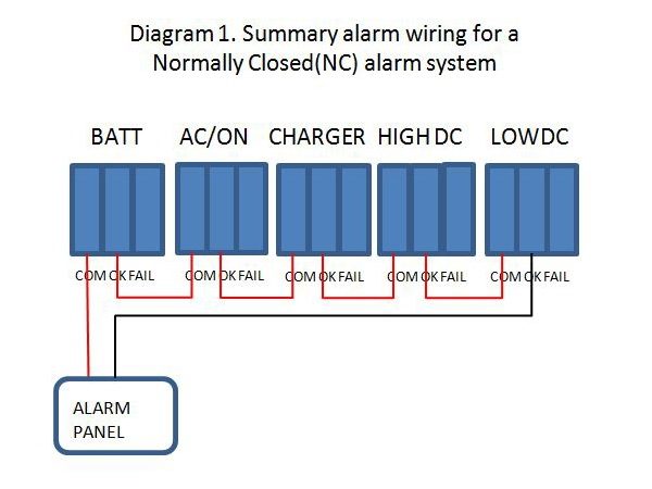
For a Normally Closed alarm system, wire the individual relays in series.  Connect the OK terminal of the first relay to the Common terminal of the next relay, and so forth down the line of contacts.  Leave the last OK open.  Include only the alarms you want in the summary. Run wires from the blank Common and the blank OK terminal to the alarm panel.  See Diagram 1.
Normally-Closed

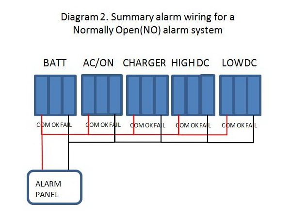
For a Normally Open alarm system, wire the relays in parallel.  Connect each of the Commons together and then each of the Fails together. Then, from one Common terminal and one Fail terminal run the wires to the alarm panel. See Diagram 2.
NormallyOpen


Critical Power Insights, Delivered

Quarterly updates, technical guidance, and industry news